Industrial Automation Systems
Industrial automation serves as the backbone of modern industry, enhancing production while boosting quality, efficiency, and safety.
The evolution of modern industrial control systems and instrumentation has empowered industries to automate complex processes and reduce labour costs.
The ongoing integration of plant floor control systems with enterprise networks for the purpose of business intelligence, is a growing and expanding trend, driven by advancements in technological capabilities.
In this article, we provide an overview of key industrial automation technologies and terminology.
What is Industrial Automation?
Industrial automation is the field of technology used for monitoring and controlling various industrial processes with limited human intervention. It involves the use of computers, robots, sensors and actuators to monitor and control production lines and processes.
There are many other definitions of Industrial Automation available online and within various published works. The following are two examples of definitions from well established technical authorities in the field.
B. R. Mehta et al provides an elaborate definition of Automation;
Industrial automation is a vast and diverse discipline that encompasses process, machinery, electronics, software, and information systems working together toward a common set of goals – increased production, improved quality, lower costs, and maximum flexibility.
Industrial Process Automation Systems Design and Implementation B. R. Mehta Y. J. Reddy 2015
ISA offers a much lighter, concise definition while succeeding to convey many of the same ideas;
The creation and application of technology to monitor and control the production and delivery of products and services
The International Society of Automation (ISA) defines Automation – https://www.isa.org/about-isa/what-is-automation.
Factory vs Process Automation?
Industrial automation generally falls into two main categories: “Factory Automation” and “Process Automation.”
Factory Automation describes the automation of manufacturing processes in a production facility. These processes are typically discrete or batch-oriented such as in Automotive or Pharmaceutical.
Process Automation, on the other hand, involves the automation of continuous processes found in facilities like offshore oil production platforms and chemical plants.
While there are other major fields of automation, such as building services and warehouse automation, this article will focus solely on industrial automation related to the production of a products and materials.
Automation vs I&C?
The term Automation is sometimes used interchangeably with Instrumentation and Control (I&C). There are variations on the usage of automation depending on the regional preference and organisations.
In general within USA and North American firms you are more likely to hear the word Automation while in Europe, UK the term C&I or I&C is more prevalent.
This is a consequence of the regional variance and culture. Also this is a consequence of how different companies are structured and how some companies tend to segregate or combine the control systems and instrumentation disciplines in different ways.
In addition – I&C is typically used more as a role based designation; to describe the responsibility of a role such as “I&C engineer” while automaton is a broader term applied to the entire field.
Commonly used Terms in Industrial Automation
- Process Automation – Automation of continuous processes.
- Factory Automation – Automation of batch or discrete processes.
- Industrial Control Systems (ICS) – Any computerised control system in an industrial facility for monitoring/control of a process either discrete or continuous, including the plant process, auxiliary packages and safety systems.
- Industrial Automation and Control System (IACS) – Generic Term used to represent any arrangement of devices and applications used for automation such as DCS, SCADA, PLC. Used extensively in ISA 99 literature and standards.
- Process Control – Describes the study of process dynamics and application of control theory for control system design and optimization. Advanced process control (APC) may be considered part of this field.
- Instrumentation – Encompasses field devices such as valves, transmitters, analyzers, etc., and designates specific roles like instrument engineers or technicians.
- Instrumentation and Control (I&C) – Describes a role or discipline within an organisation covering both instruments and control systems.
- Electrical and Instrument (E&I) – Typically used for the designation of technicians/engineers with responsibilities for maintaining or commissioning both electrical and instrumentation equipment.
What is Industrial Automation Engineering?
Automation Engineering is a multidisciplinary field that involves the design, development, implementation, and maintenance of automated systems within an industrial environment.
Automation Engineering is a young field of engineering relative to Mechanical and Chemical engineering fields. Automation engineering has taken some time for its identity to be recognized as a distinct field of engineering.
For a long time in universities, Automation and Control was part of the department of Electrical or even Chemical engineering.
Now of course universities have established dedicated automation departments or the courses are offered under the more appropriate department of Applied Physics.
Industrial Automation engineers and technicians typically draw upon a wide array of technical skills such as;
- Industrial Control Systems (ICS)
- ICS Networks
- ICS Cybersecurity
- ICS Integration – Supplier Packages & Instrumentation
- IT/OT Integration
- Software Programming and IT
- Field Instruments
For more information how to get training and skills in Industrial Automation or to improve your career prospects read here.
Components of Industrial Automation Systems
The components of a modern industrial automation systems can generally be classified into three groups;
- Sensors or Transmitters: These devices measure and monitor various process variables within the field.
- Control Systems: Computerized systems responsible for reading and interpreting the transmitter output and executing predefined actions to modulate the process through means of a final element. In addition these systems provide an interface for operators to monitor and control the plant process.
- Actuators or Final Elements: Devices such as valves, motors, fans which carry out the actual control actions in the field, modulating the process based on an signal from the control system.
In the next section we will look into the details of each of these components.
Sensors, Transducers and Transmitters
The definitions of sensors, transducers, and transmitters, as well as their applications, can sometimes be confusing.
These terms are not always used correctly, and often the term “transmitter” is used broadly to describe the entire assembly of a measurement device, which deviates slightly from the definition described in standards.
Rather than attempting to create new definitions and create more confusion, for this article, we will directly quote from ISA.
What is a Sensor?
The primary sensing element (sensor) is normally the initial point of contact with the physical quantity. The sensing element was first formally defined in a standard by by American National Standards in 1966;
“The system element that quantitatively converts the measured variable energy into a form suitable for measurement.”
American National Standard C39.4–1966, Specifications for Automatic Null-Balancing Electrical Measuring Instruments
The most recent definition provided by the ISA in their standard for Instrumentation Symbols and Identification is;
A separate or integral part or function of a loop or an instrument that first senses the value of a process variable, that assumes a corresponding predetermined and intelligible state, and/or generates an output signal indicative of or proportional to the process variable; see also detector and primary element.
ISA 5.1 2009 – Instrumentation Symbols and Identification
What is a Transmitter?
Within an instrument assembly the transmitter is typically the second element which interfaces with a sensor and provide a standard measurement output to the control system.
The formal definition provided by ISA;
A device that senses a process variable through the medium of a sensor or measuring element and has an output whose steady-state value varies only as a predetermined function of the process variable
ISA 5.1 2009 – Instrumentation Symbols and Identification
Standard transmitter outputs can combination of 4-20mA, HART, Fieldbus and others. Most modern field instruments will utilize HART protocol for reading device diagnostics.
For process variable readings the standard 4-20mA output is still extremely common due to its robustness against interference and noise. HART signals are easily modulated over 4-20mA and are used by many instrument manufactures to interface with instrument Assets management systems (AMS).
In addition a complete transmitter assembly will generally include Signal Conditioning and A/D conversion.
What is a Transducer?
Tranducer is generally considered any device which translates a signal from type to another with a known input out relationship.
Therefore the term transducers can be equally applied to sensors and transmitters if they are performing this function of signal conversion. The formal definition provided by Ref ISA;
A general term for a device, which can be a primary element, transmitter, relay, converter or other device, that receives information in the form of one or more physical quantities, modifies the information or its form, or both if required, and produces a resultant output signal.
ISA 5.1 2009 – Instrumentation Symbols and Identification
Measurement Device Selection
Choosing the correct measurement instrument requires a detailed evaluation of the process variable properties and the surrounding environmental conditions, taking into account all potential operating scenarios within the plant
Automation Engineers must collaborate closely with their Process Engineering discipline to fully understand the design intent and select a measurement device model that aligns with it.
In addition the local environmental conditions, regulations and complexity of control system integration should be considered important.
Some considerations and selection criteria used by Automation Engineers for transmitter selection are;
- Process Variable – The type of process variable and engineering units to be measured by the control system and displayed on HMI to the operator, such as level, flow, temperature, %LEL, %O2 ect.
- Process Variable Measurement Range – Anticipated process envelope, alarm/trip setpoints, and any specific requirements for measurement range specified by process discipline.
- Process Fluid Properties – Newtonian or non-Newtonian composition, homogeneity, conductivity, density, compressibility ect.
- Environmental Conditions – Evaluating the devices body and probes exposure to temperature, water ingress, corrosion, erosion, vibration, EMF.
- Functional Safety Requirements – Relevant to transmitters which form part of a SIF, ensuring the device is SIL certified and that specified failure rate is low enough to achieve the required SIL target defined by LOPA or SIL Assessment outcomes.
- Compliance Obligations – Regional, international standards or end-user requirements related to the measurements devices performance, construction, material composition, Ex ratings ect.
- Maintenance Constraints – Anticipated constraints on the devices maintenance frequency or proof test frequency based on the availability of local maintenance teams and accessibility device location.
- HART Compatibility – Assessing compatibility with systems like Asset Management, Multiplexers or any other interfaces intended for HART communication. Assessing the availability of device definition files and requirements for device templating to develop new files.
- Interface Compatibility – Ensuring compatibility of I/O modules, fieldbus cards, serial cards of the Industrial Control Systems (ICS) intended to be used.
- Application Software Requirements – Evaluating the scope and complexity of any application software development required to fully integrate the device into the target DCS, PLC, or RTU. This involves assessing the requirement for development and prototyping of new software topicals in the control system that will be used to read the measurement device.
Final Control Elements
A final control element is defined as a field device that physically changes a process in response to a change in the control system setpoint. Final control elements relevant to actuators include valves, dampers, fluid couplings, gates, and burner tilts to name a few
Control Valves
Control valves are among the most encountered final elements in automation systems, the most common types are globe or rotary valves.
Control valves are matched with adequately sized actuators to ensure sufficient torque for the valve to stroke within the necessary operational parameters. Smaller valves, like needle or solenoid valves, are utilised for low-flow or pilot applications.
Selecting and sizing control valves is a critical aspect of automation system design, impacting process gain and efficiency. The selection of control valves involves a meticulous assessment of system dynamics and process design.
Dampers
Dampers are used to control the flow of air within ducting pipework and typically used in HVAC systems within a facility to maintain optimum environments for the process and automation equipment.
They can be used to regulate or to isolate airflow such as for zoning air conditioning systems in large building. Dampers can have both electrical and pneumatic actuators.
Dampers are also used for active fire and gas protection systems for isolating accommodation areas during emergency situations and shut off the inlet air-flow and preventing ingress of toxic gases to the accommodation.
Variable speed Drive
Variable speed drives (VSD), also known as Variable Frequency Drives (VFD) or AC drives, serve a fundamental purpose in controlling energy flow from the mains to various processes. Positioned between the electrical supply and the motor, these drives regulate the power transferred to the motor.
Control of VSD from the automation system may be done using a field bus card to communicate directly with the device or simple hardwired analogue outputs to provide a RPM setpoint. Normally the important ramping and other functions is done within the VSD itself.
Relays and Contactors
Relays and contactors function as switches for discrete control of equipment and power supplies. Typically, a relay’s contact is controlled by a coil energised by a 24V control signal from the automation system.
They are widely used in industrial automation to control pumps and manage infacing signals such as between DCS and PLCs. Contactors, handling loads above 10A, are commonly used for de-energizing equipment, especially in safety shutdown systems, often configured as Normally Open.
Both rely on electromagnetic principles. However, relays offer varied configurations for control and field circuits, featuring options like normal open/closed settings and time-delays.
When selecting relays and contactors, compatibility with PLC/DCS digital output channel current and line fault detection (ETA) should be considered.
Motors – Pumps, Fans, Compressors
Motorized equipment such as pumps, fans and compressors are commonly used as final element in automated control strategies deployed by industrial control systems.
A typical configuration is a 24V DC signals from the control system I/O card is used to control interposing relays the switchgear enclosure (commonly referred to drawer or cubicle). The exact interface and architecture will vary depending on the facility and the end-users preference for their electrical design.
It is often more efficient for cabling purposes to route all motor control signals to a bank of relays in a purpose-built cabinet for switching low voltage motors. This panel is often referred to as an Interface Relay Panel (IRP).
In other cases the interface between control system and motors can be achieved over serial link or fieldbus. In such case the switching of the drives is managed by local PLC (normally part of a power management system (PMS) such as ABB which stop/start commands are relayed across the serial link.
The motor status and relevant diagnostic information is handed back across the serial link and relevant software typically are configured in the control system to properly read and present the data back to the operator over HMI.
Serial link interfaces obviously remove an extensive amount of wiring from the design, however, the integrity of the serial link should be optimised. This can be achieved though the use of redundant serial link topologies with network switches that support Parallel Redundancy Protocol (PRP).
In facilities were functional safety is part of the design basis (such for Oil and Gas) signals for remote emergency shutdown on facilities were functional safety will generally need to be maintained as hardwired.
Servo Motors
Servo motors are often deployed by automation systems as part of a final element which requires motion control. Typical examples of this include; CCTV camera pan and tilt adjustment and robotic arms in assembly stations.
Servo motors are extremely prevalent in the manufacturing industry which relies heavily on motion control systems for carryout repetitive tasks such as sorting, assembling, painting, cutting ect.
Servos motors produces motion in response to a command, regulates the speed and direction in response to feedback. The feedback is commonly achieved with an encoder that provide position feedback and is embedded within the motors assembly.
For the specification of motors there are two 3 distinct classification of motor;
- AC/DC Motors
- Synchronous or Asynchronous
- Brushed and Brushless
The selection of motor type is highly dependent on application, initial cost and maintenance cost, required lifespan. In general the use of AC type motors is more prevalent in industrial facilities.
Servo motor control is achieved by a control system which generates the command for speed and position via an analogue output or digital fieldbus signal. The commands are received by an amplifier that generates the required AC frequency to manipulate the motor. In some cases, the amplifier and controller are combined.
The servo motors are attached to mechanical actuators for converting the rotational action to linear action or other forms. In general there are two categories of actuator – rotary and linear.
The design of the motion control system and the type of actuators used depend heavily on the application. This can range from a simple servo used to rotate a CCTV camera to a complex 6-axis robot arm used in automobile assembly.
Industrial Control Systems (ICS)
ICS are responsible for executing control functions and providing interfaces for operators and engineers. This collective term is extensively used to describe any computerized control device and associated network hardware infrastructure employed for automation purposes. Generally, there are three commonly accepted classifications of ICS: PLC, DCS, SCADA, and associated network infrastructure.
Programmable Logic Controller
PLCs were developed in the early 1960s and first utilised by General Motors as a solution to avoid re-work of relay assemblies during the changeout of production lines.
A programmable logic controller is an industrially hardened computer-based unit that performs discrete or continuous control functions
Inst Engineers HB – Process control – Section 5.4
Where are PLCs used?
PLCs, or Programmable Logic Controllers, are frequently utilized to automate smaller processes involving discrete input and output signals. They play a significant role in factory automation, particularly in scenarios where production consists of standalone units across various assembly lines. For instance, BMW manufacturing plants predominantly rely on Siemens PLCs to automate automatic assembly stations and conveyor systems.
In process automation, PLCs are often employed alongside Distributed Control Systems (DCS) to manage the control of auxiliary systems. This is a common practice, especially when these auxiliary systems are supplied by specialized third-party vendors with an existing proven PLC setup.
Other industries were PLCs find good application are;
- Automotive – automotive manufacturing plants for managing assembly lines, controlling robotic arms, conveyor belts.
- Papermill – processing, paper rolling machines, cutting systems, and packaging units
- Brewery – managing bottling lines, regulating mixing and batching processes
- Manufacturing – metalworking, plastic manufacturing, food production and packaging
Warehouse Automation – More recently PLCs have found good application in the fast growing sector of warehouse automation. Most major online retailers and supermarkets have adapted to automating much of their warehouse operations. These PLCs manage the movements of the automated handling equipment and carts, operating in large warehouse facilities to efficiently prepare customer orders.
Package Equipment – PLCs are also used extensively by suppliers of auxiliary plant equipment (packages) which are used to support the plant operations such as HVAC, Air Compressors, Generators ect. These types of packages are normally provided as a black-box solutions and integrated to the main plants control system.
PLC vs DCS Controllers – Due to modern PLC(s) capability for peer to peer communication between CPU(s) and improved HMI, they can technically be deployed as a plant wide Distributed Control System (DCS). This type of deployment is well suited for smaller to medium-sized manufacturing plants that need to undertake frequent modification or changeout of the assembly lines and which have automation teams embedded in the workforce to manage this.
What are the basic components of PLCs?
- Central Processor Unit (CPU) – Scanning I/O bus, traffic control, application program execution
- Memory- Stores both the PLC’s executive program and the process specific application program used to monitor and automate plant equipment.
- I/O Cards and Modules – Discrete, Analogue inputs and Serial cards amongst many other possibilities. Also available are remote I/O cards located in downstream junction boxes.
- Power Supplies – Converts incomer supply voltages to those required by the PLC backplane. Also provide grounding and isolation to protect the sensitive PLC components.
- HMI and Operator Workstations – Display providing control and monitoring of the process for plant operators and technicians.
PLC Communications Networks
Modern PLC manufacturers provide products with advanced peer-to-peer communication capabilities, enabling PLCs to communicate across multiple process areas using protocols such as ControlNet and DeviceNet.
The evolution of peer-to-peer communications has facilitated the distribution of PLCs across plants for the control of various process systems. This has been referred as a cross pollination of technology originating from Distributed Control Systems (DCS).
The capacity for PLCs to communicate across the entire plant and reference the status of other process variables significantly reduces the need for additional I/O points.
The emergence of peer-to-peer networks, such as AB DeviceNET introduced in 1994, along with advancements in PLC technology, has narrowed the gap between PLCs and DCS, to the extent that most applications can now be handled by both systems.
What Programming Language do PLCs use?
The most commonly encountered PLC programming language is ladder logic (LD). Ladder logic revolutionized the field of PLC programming and hiked the popularity of Modicon 084, the first PLC in the 1960s. There are five internationally acceptable PLC programming languages under IEC61131-3.
Instruction List (IL) – Instruction List is a low-level PLC programming language resembling assembly language, as it is low level and deals directly with memory assignments. It uses mnemonic codes and is suitable for writing simple programs with specific control instructions.
IL has advantage due to its speed, as it can be optimized similar to assembly language it requires not interpreter. However IL is not often well understood or practiced outside of computer science communities and therefore most PLC technicians will not be comfortable with this.
IL is made available by many PLC manufactures, however, it is almost uniserialy never practices. We note that Instruction List has also been marked for deprecation in future editions of IEC61131-3.
Structured Text (ST) – Structured Text is a high-level programming language resembling Pascal or C. It allows for complex programming, mathematical computations, and algorithm-based control. It’s ideal for more advanced and complex applications. Traditionally used when a high level of arithmetic or computation is required.
Ladder Logic (LAD) – Ladder Logic is the most commonly used programming language for PLCs. Its graphical representation, derived from relay drawings, contributes to its enduring popularity. Ladder Logic is best suited for discrete logic control and sequential operations. Traditionally used for basic discrete machine control and is popular with suppliers of third party package equipment such as Compressors, HVAC, HPU skids.
Despite the evolving technologies, Ladder Logic still maintains a strong following within the automation community. Many integrators and end-users continue to standardize their plant PLC development with Ladder Logic due to its widespread understanding and accessibility, particularly among electrical disciplines.
The ability to troubleshoot online, with the capability to observe the live execution, remains a significant advantage. The graphic representation of Ladder Logic facilitates quicker and easier troubleshooting compared with structured text which is based on object-oriented software.
Function Block Diagram (FBD) – Function Block Diagram uses graphical blocks to represent functions and their interconnections. It’s suitable for modular programming, allowing engineers to reuse code blocks for various applications.
Sequential Function Chart (SFC) – SFC is a graphical programming language used for sequential control tasks. It represents sequences of operations, states, transitions, and actions within a system. It is used extensively for batch control, such as pharma and breweries. SFC is used in process industries for automating plant start-up (such as opening valves and starting pumps in a predefined order).
It may be argued that SFC is not really a language, more it deals with directing the flow and execution of lower level software modules.
For detailed information on the best e-learning courses available to learn or improve your PLC programming skills, check out our list of the best value PLC training courses here.
Distributed Control System (DCS)
A Distributed Control System (DCS) is an automation technology that employs autonomous controllers distributed throughout a plant. These controllers operate independently, without the need for central supervisory control. They communicate with each other across the plant using peer-to-peer communication via a high-integrity redundant internal communications network.
The physical DCS controllers are typically housed in panels, often located in HVAC-cooled rooms at various points around the facility, near the process equipment and instrumentation.
The deployment of DCS controllers within enclosures across a facility is also becoming increasingly common. This is due to advancements in DCS technology, which have led to reduced footprint and programmable I/O capabilities.
Where is DCS used?
Distributed Control Systems (DCS) find application in medium to large-scale process plants that utilize continuous or batch processing, including:
- Offshore Oil and Gas Platforms: Used for oil and gas separation, production control, and safety systems.
- Oil Refineries: Employed in crude oil distillation towers, hydrocracker units, and burner management systems.
- Chemical Plants: Utilized in reactors, mixing and blending units.
- Pharmaceutical Industry: Applied in reaction vessels, filtration and purification units, and tablet presses and coaters.
- Power Plants: Employed for turbines and generator control, as well as emissions control systems.
DCS serves as an effective automation solution for end users who need to address various concerns and end user requirements in plant design, such as:
- Ensuring high system availability and production uptime.
- Implementing redundancy in the communications network.
- Managing high complexity processes involving a large number of control loops.
- Handling large batch processes with high-value products.
- Meeting stringent safety requirements, such as IEC61511 compliance.
- Adhering to regulatory standards like Good Manufacturing Practice (GMP) for the production of drugs.
- End-User preference of a “Single Supplier Solution” for engineering, commissioning and maintenance (full life cycle support).
- End-User preference due to their familiarity with DCS in existing facilities and already having an large corpus of specifications and workflows developed around DCS.
Unlike Programmable Logic Controllers (PLCs), DCS is typically designed and integrated by large automation contractors, often the same entity that developed the product. The design and delivery of DCS is normally executed within the framework of a comprehensive engineering contract, including hardware and network design, as well as third party integrations.
DCS products normally include a large suite of software applications that serve purposes far beyond basic plant control, such as alarm management, instrument loop tuning, and process control optimization.
Large-scale DCS systems are less prevalent within factory automation, notably in the automotive industry, due to the well-established expertise in utilising PLCs for assembly line automation.
For an overview of market-leading DCS products, check out our comprehensive guide – The Big List of DCS Offerings from Major Automation Contractors
What are the basic Components of DCS?
The following are key components that characterise a modern DCS installation.
- Operator Workstations – Used by plant operators for process monitoring and control. They incorporate software packages such as HMI for process graphics and faceplates, process variable trending, production reporting and events journals.
- Engineering Workstations – Used by plant technicians or commissioning personnel to configure, troubleshooting and maintenance. Typically an engineering workstation will host proprietary software needed for system configuration, network diagnostics and for monitoring the condition of smart instrumentation devices.
- Controllers – Modular electronic components containing CPU and Memory to execute the application software and communicate with I/O modules on a backplane or remote I/O located within field enclosure.
- Application Software – Logic executed in the controllers for monitoring and controlling of plant process and batch production. Application software related to functional safety is executed on SIL rated logic solvers and segregated electronically from process automation.
- I/O (Input/Output) Modules – Modular electronic components for interfacing with plant instrumentation and field desives. Most DCS suppliers also offer smart IO products for flexible online I/O changes without major adjustment to the backplane assembly (such as Emerson DeltaV Charms).
- DCS Communication Networks – Peer to peer information exchange between control modules, operator consoles and all other network nodes. Network segregation is implemented for functional safety systems.
- Firewalls and Cybersecurity – Modern DCS systems implement robust cybersecurity measures including firewalls, access controls, and authentication protocols. External interfaces are secured using firewalls, closely monitoring TCP traffic. Internal safeguards, such as the Emerson DeltaV™ IPD(s) protect controllers from potential cyber threats, inhibiting the spread of malware attacks across the network.
- History Collection and Storage – Automated collection and archiving of process data, and alarms and events record and other system performance logs.
- Smart Instrument Management Database – Server based application providing a comprehensive overview of all accessible Smart I/O and multiplexers within a hierarchical structure. It serves as a tool for plant technicians, enabling them to commission, calibrate, and troubleshoot HART-enabled devices directly from the Engineering Workstation. Additionally, it often includes smart commissioning capabilities, aiding in loop testing even before the installation of application logic.
- Advanced Process Control (APC) – Embedded applications for advanced process control functions such as plant control optimization, predictive control modelling, PID loop tuning.
- Backup and Recovery Servers – Automated image backups of server nodes and crucial equipment are performed remotely from a dedicated server running applications such as Acronis Cyber Backup.
- Main Server – Server running proprietary applications and toolsets for managing the DCS including network administration and access control. The main server will host a database containing the application software which is downloaded to plant controllers.
- Domain Controller – Server with application for management of host server blades such as Emerson DeltaV Virtual Studio or ABB 800xA VMware ESX. Used by integration teams for managing resource allocation of virtualized workstations and servers.
What Programming Language is used in DCS?
In modern Distributed Control Systems (DCS), a combination of Function Block Diagrams (FBD), Structured Text (ST), and Sequential Function Chart (SFC) programming languages is utilized. For tasks involving transmitters, actuators, and drives, a blend of FBD and ST is typically employed within modules, while SFC is reserved for higher-level control sequences like startup or batch operations.
In safety-critical scenarios with SIL rated loops, the software development is normally restricted to use FBD with predefined function blocks. Adherence to safety standards like IEC61511 mandates the use of Limited Variable Language (LVL) for application logic development, with interpretations varying among engineering contractors.
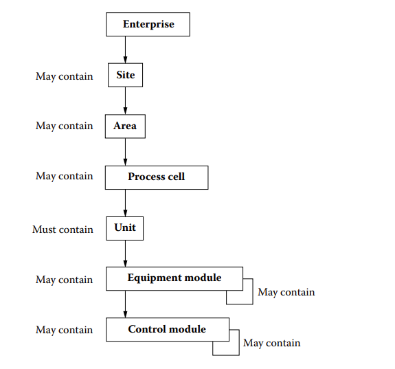
Modern DCS products commonly organize their software database hierarchy according to the ISA 88 layers model for process control, which categorizes equipment and process tasks hierarchically.
The DCS application program is structured in a specific hierarchy comprising areas, process units, and modules. Application logic for each device or equipment is typically contained within modules. Adhering to a hierarchal process model that reflects the actual plant is vital for structuring the code and logic for manageability.
Segmentation of different plant units, process trains, and other areas within a plant is essential for applying appropriate alarm management. This segmentation allows for tailored alarm management and user access adjustments for each plant unit, particularly useful during ongoing commissioning works or when equipment is out of service while the plant remains operational.
DCS systems are usually equipped with extensive libraries of function blocks and module classes for standard industry applications. Additionally, end-users often maintain their libraries of software classes for reuse across different facilities.
Programming of DCS application logic is carried out using proprietary or configuration applications provided by DCS vendors, such as Emerson DeltaV Control Studio or ABB 800xA Control Builder.
PLC vs DCS Selection
Historically, PLCs were the go-to choice for discrete I/O applications like motor control centres. However, advancements in PLC technology have minimized the gap between PLCs and DCS, often making the decision between them reliant on user familiarity.
The emergence of peer-to-peer networks, like AB DeviceNET in 1994, has further blurred the lines between PLCs and DCS, allowing for the distribution of PLCs across plants and contributing to their convergence. Despite these advancements, subtle differences between the two technologies still exist
Adaptability and Scalability – Both PLCs and DCS suppliers offer a wide array of I/O cards and modules for interfacing with transmitters, actuator and speciality applications.
Modern DCS with electronic marshalling and virtualized workstations are a good solution when the system footprint needs to be minimised, such as for offshore production platforms.
Scalability is also a big strength of DCS systems, due to the emergence of electronic marshalling and high capacity industrial networks.
Built-in Applications – Top-tier DCS solutions will include a large suite of applications and function for plantwide lifecycle support. Some examples include;
- Instrument Life Cycle – Instrument asset management database for automated loop testing, configuration of HART devices, positioner calibration.
- Advanced Process Control – Applications with a suite of end-user tools for process optimization through APC methods and management of PID loops.
- Alarm Management – Built-in user friendly applications for alarm management enabling the end user to monitor the system alarms performance against benchmark standards and execute rationalisation activities.
Industry Tailored DCS Solution – Several leading DCS suppliers offer industry-specific solutions like Emerson Ovation or GE Mark Vie which are optimised for power plant automation. These DCS products have been developed through strategic acquisition of sector focused-automation companies with decades of integration experience and industry proven technology.
End-User Budget – The decision to purchase PLCs or a plant wide DCS solution should consider factors like facility size, project budget, and user familiarity. PLCs are typically suited for small to medium-sized facilities and moderately complex processes.
Safety and Quality Compliance – Automaton system and component selection will also be driven by compliance with regional standards and end-use specifications that underlie the facilities basis of design. In addition, the automation supplier’s experience in delivering a system within the framework of key international standards is a major factor for consideration.
Turnkey or Phased Delivery – The end-user’s involvement in integration and their familiarity with the product will significantly impact the choice between PLCs and DCS.
Many end-users have internal automation teams to handle their integration activities and do not require the kind of holistic plantwide solution offered by DCS suppliers.
Other end-users will require complete turnkey solutions provided by EPC contractors and major automation suppliers.
Facilities operating with a strong automation team embedded in the workforce may be more adapted to overcome any challenges of implementing plantwide automation systems using PLC(s).
Automation Supplier Track Record – Ultimately the automation supplier’s expertise and experience of successfully delivering systems within specific industries and operating environments will play a major part in the end-users selection.
A poorly executed system integration will have long term consequences for the plant efficiency, quality and safety, irrespective of the chosen technologies.
Supervisory and Data Acquisition System (SCADA)
SCADA consists of a collection of computers, sensors, and other equipment interfaced by telemetry, to monitor and control processes
INST ENG handbook Process Control and Optimization 2006 4th Edition.
SCADA is an industrial computer system for monitoring and controlling a process, consisting of the following elements;
- Human Machine Interface (HMI)
- Remote terminal units (RTU)
- Programmable logic controllers (PLCs) and /or Distributed Control Systems (DCS).
- Communications and network infrastructure
Modern SCADA – More Than Plant Automation
Traditionally the term SCADA was used to infer an automation system for controlling and monitoring the process on the shop floor level.
However, with recent improvements in PLC HMI technology and the evolution of modern DCS, the domain of SCADA has moved away from the shop floor automation system and become a supervisory tool used at enterprise level. It is now more common that PLCs and DCS with integrated HMI are used for the local automation and operation of the facility.
SCADA HMI is often used for observation at an enterprise supervisory level and is typically only used for control purposes in the absence of a local manned control room for control actions that cannot be automated by PLC(s).
Modern SCADA products are typically marketed as an “enterprise solution” operating at a layer above the DCS/PLC domain and for monitoring multiple facilities spread out across large geographical regions and used by company personnel outside of the plant’s operations team.
The number of PLC(s), RTU(s), DCS(s) and many other possible data sources interfacing to the SCADA server; the quantity, type and regional distribution of these will vary wildly depending on the application.
Some examples of SCADA products are;
- Emerson Open Enterprise Suite
- AVEVA Enterprise SCADA
- GE – CIMPLICITY
- GE – iFix
What is SCADA Used For?
SCADA is typically used for the following applications involving monitoring and control of multiple plants or facilities across multiple regions. Some of the larger implementations can have over a million tags and can accommodate access for hundreds of users through dedicated workstations and web applications.
Some examples of use cases are;
Water/Wastewater – Control and Monitoring of Regional and National Water/Wastewater infrastructure – Dams, Weirs, Water Treatment Facilities.
Oil and Gas Pipeline Management – Monitoring and controlling oil and gas pipelines. They oversee pipeline flow, pressure, temperature, and detect leaks or anomalies, ensuring safe and efficient operation.
Transportation Networks – Monitoring of the automation software system from GE monitors nearly every electronic device related to the business of moving train. The system manages millions of real-time indications coming in from the field – including field signals, power indications, hazards, network switch diagnostics, and PLC / controller diagnostics.
Power Generation and Distribution: Application: SCADA manages power generation and distribution networks. It monitors grid parameters, controls power flow, and detects faults or outages for rapid response and restoration. Functions: Load balancing, voltage regulation, generator control, switchgear monitoring, fault detection, and outage management.
SCADA for Control Applications
SCADA systems are more optimised for monitoring large numbers of tags and storing, organising the plant data for enterprise users. However, SCADA is also utilised in various ways for the purpose of controlling process field devices and production. The extent to which SCADA is used for directly controlling the process through operator actions will also depend highly on the application.
SCADA is used for the purpose of controlling plant equipment in cases where the facility has no permanently manned control room but still requires some regular operator actions to control valves and other equipment. Such operator initiated actions are those which cannot be automated as they are in response to an emerging scenario such as alignment with changes in commercial obligation, or unforeseen environmental, safety, political factors that impact the facilite(s) production.
- Wastewater Industry, the SCADA system may be used to control the level of weirs and to open/close valves across large regions for managing water suppliers.
- Electrical Power Substations, which require infrequent switching of high voltage contactors.
- Oil and Gas Pipeline management – Where valves and chokes located in remote regions must be regularly modulated and it is not practical or safe to be done locally.
 See our comprehensive article on SCADA careers
SCADA and MES
In Manufacturing and Pharmaceutical Industries – Which are characterised by discrete and batch control, the SCADA may also be used to interface with Manufacturing Execution Systems (MES) for receiving production targets and batch orders from business ERP systems and communicating these to the shop floor automation system.
There has also be some recent trends to incorporate MES function directly into the SCADA products, this has been done by some SCADA suppliers who provide ready to use software module for interacting with ERP systems, supporting MES functions such as production scheduling.
What are the Basic Components of SCADA
The term SCADA when mentioned in supplier marketing literature, normally refers to the actual software suite hosted offsite on a server, which at a most basic deployment will consist of a database, historian and a HMI.
However a full SCADA deployment if if considering every data producer, may contain any combination of devices including industrials computers, DCS and PLC, spread out over a region either within a facility across a large geographic region.
Central SCADA Server – Collects and processes data from RTUs, PLCs and other data producers, provides visualisation, and executes control functions. User interface may be provided in the form of dedicated terminals and industrial hardened tables. Normally the main SCADA will contain historian features and a relation database database.
SCADA server can be located physically onsite, offsite on company enterprise network or even hosted in cloud.
Database/Storage System – Stores historical data, alarms, events, and other system information for analysis and reporting. Examples of populate database systems used be SCADA manufactured are SQL databases (MySQL, Microsoft SQL Server), Historian systems (OSIsoft PI System, GE Digital Historian).
Human-Machine Interface (HMI) – Provides a graphical interface for operators to visualize processes, alarms, trends, and control system components. Examples: Ignition by Inductive Automation, Wonderware by Aveva, WinCC by Siemens.
Most modern SCADA packages have options for remote web access. This allows for personnel to run the from their laptop or tablet while performing maintenance onsite within plant WIFI network such as Proficy Webspace. In addition SCADA access is often made available to enterprise users through dedicated web applications hosted on the enterprise network.
Data Producers – This may include any node with the SCADA network that is providing some kind of data input; PLCs (Programmable Logic Controllers), RTUs (Remote Terminal Units) and even DCS may be interfaced to SCADA.
RTUs may be described as similar in function to PLCs but designed specifically for remote applications, often in harsh environments. Examples include Schneider Electric SCADA Pack RTUs, Siemens SIMATIC RTUs, Emerson ROC RTUs.
Many RTU products are developed and markets for specific applications such as pipeline integrity management, wastewater and and power network management.
DCS – SCADA Bridges – Software applications to support inter-operability between facility DCS and SCADA system, may be referred to as “bridges”. Examples is “DeltaV RTU Connect” which enables real-time data, alarms, and historical logged data to stream from the OpenEnterprise SCADA system to the DeltaV DCS allowing for data exchange and conrol to be executed from SCADA.
DCS vs SCADA with PLCs
Historically, DCS and PLC/SCADA technology differed enormously. DCS systems were characterized by slower processing times (around 1 second per module) until the early 2000s and were designed to control large continuous processes.
However, recent developments have led to DCS systems becoming more scalable as suppliers sought to enter smaller markets where PLCs dominated. Some DCS suppliers have even developed their own PLCs with equivalent scan times and processing capabilities, which seamlessly integrate into the DCS network (e.g. DeltaV PK controller).
PLCs technology has also evolved to handle more analogue logic and programming in function block code. With PLC suppliers providing integrated HMI solutions and improved networking capabilities, PLCs can now be deployed in a manner resembling DCS systems.
Despite the convergence in technological capabilities, there are still significant differences between SCADA and DCS. These products retain some nuanced distinctions, particularly in their specific use cases and optimization for certain applications.
Live System Changes, DCS systems were specifically designed to allow online changes without requiring shutdown and impacting production. The modular nature and redundancy allowed for significant software changes and firmware upgrades to be implemented without shutdown.
This has not always been the case for PLCs and although online changes are possible, there are still some extensive limitations and generally the culture is that vendors and suppliers of such equipment will not endorse online changes or give clear assurance of system availability.
Software Module Scan Rates, In DCS systems, the processing scan times for modules and IO channels are typically much slower compared to PLCs. For Basic Process Control System (BPCS) applications, the minimum scan rate is around 1 second, while for safety logic solvers modules, it’s around 50 milliseconds.
Managing scan times in DCS systems is crucial, as higher scan rates for a large number of tags can significantly impact controller performance. Careful resource planning is necessary to ensure that scan rates are appropriately selected for the intended control application.
In PLCs like the Allen-Bradley ControlLogix or CompactLogix (Logix 5000 series), the execution cycle involves scanning through the entire program sequentially, typically multiple times per second. However, unlike DCS controllers, PLCs don’t have a direct setting to specify a fixed or precise scan time.
DCS controllers often use a time-triggered or event-triggered methodology instead of a cyclic scan. For instance, the Emerson DeltaV S-series controller offers a minimum scan time of 100 milliseconds. This limitation isn’t usually problematic for continuous processes like oil and gas processing, where process dynamics change gradually across large vessels.
However, for applications requiring fast controller loop response, such as seal gas pressure control and anti-surge valve control, PLCs are more suitable due to their lower available scan times.
Single-Supplier Model vs Independent System Integrator: Some End-Users may have a preference for a single supplier to provide their automation solution.
SCADA systems integrations often involve multiple suppliers or vendors for different components like HMI/SCADA software, PLCs, RTUs, sensors, and communication systems. This requires may imply more risk to the end-user in terms of managing licencing, support and and maintenance.
DCS solutions often come from a single major supplier, offering a unified ecosystem. DCS solutions are commonly engineered and delivered as a comprehensive package by major automation suppliers.
SCADA solutions are often pieced together by integrators or project teams from components provided by different suppliers, offering greater flexibility but requiring more integration effort.
IO Capacity and Licensing, SCADA and DCS designs have very different implication for IO capacity. SCADA solutions typically offer the flexibility to accommodate almost unlimited I/O count, usually to the extent of server capacity. Unlike DCS, where I/O is normally restricted to a pay-per-tag licensing model.
This distinction is particularly significant in large-scale deployments, such as infrastructure management systems, where SCADA needs to manage over a million tags. In contrast, such a scale would be impractical or too costly within a DCS deployment due to the tag-based licensing model imposed by many DCS vendors.
Inside or Outside the Fence Solution, A commonly accepted distinction within the automation community is that SCADA products are typically optimized for higher-level, multi-facility supervision, whereas DCS is more tailored for local control within a single facility.
In its comparison with DCS, the modern SCADA product may be referred to as an “outside-the-fence” solution, as it is better optimized for geographically dispersed environments. It serves to link plant floor processes with business management tools, emphasizing data acquisition and collation for business intelligence.
It’s important to note that there are exceptions and many SCADA deployments are used for shop floor automation, particularly in manufacturing industries.
Industrial Automation Networks
An industrial control network is a system of interconnected equipment used to monitor and control physical equipment in industrial environments. These networks differ quite significantly from traditional enterprise networks due to the specific requirements of their operation.
This has resulted in a situation where engineers involved in the design and maintenance of control networks must be familiar with both traditional enterprise concerns, such as network security, as well as traditional industrial concerns such as determinism and response time.
ISA 95 Framework
The ISA 95 Layer Model (UML) model is used as a basis for the development of interfaces between plant floor equipment and enterprise. The understanding of ISA 95 layer model is important
ISA-95 incorporates the layers model of technology and business process for manufacturing enterprises as levels for the standard. Each layer has different requirements for the volume of exchange data, speed and determinism.
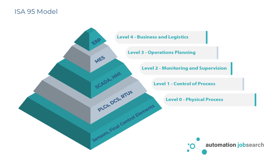
Level 0 – Field Devices – used to control and monitor the physical process such as –
- Transmitters
- Actuators and Valves.
Level 1 – Field Devices – Devices involved in sensing and manipulating the physical processes; refers to
- Smart Positions
- Drives
- Motion control amplifiers
- Servo Motors
Level 2 – ICAS – Equipment used for collecting the input from field devices and/or programmatically determining control actions for actuators, valves, drives and other final element devices such as;
- DCS controllers
- PLC(s), RTU(s)
- Industrial Computers
- Operator Workstations
- DCS/PLC Plant level Network Switches
- Wireless Field Receivers
- DCS Server racks
Level 3 – Operations Management – Equipment and applications used by facility operation team to manage the process and plan and schedule maintenance of the IACS and other plant equipment.
- DCS Remote Access Servers
- MES Servers
- PI Historian Server
- Applications for management of IACS software changes, electrical isolations, control of work (permit systems).
DMZ – Typically a comprehensive Industrial Demilitarized Zone will be located between Layer 3 and 4.
Level 4 – Enterprise level – Equipment and applications for business-related activities needed to manage a manufacturing operation. Such as;
- ERP Business Systems such as SAP, Oracle
- Commissioning/Completions Databases systems
- Asset Change Management systems
- Email, web services
- Security Services – Active Directory
Industrial vs Enterprise Networks
While examining Industrial Control System(ICS) networks, it is helpful to understand the differences with conventional enterprise networks by considering the dependencies, design constraints, and different drivers for security and availability.
Understanding the nuances of these differences can help our understanding of IACS networks as automation engineers.
This section aims to highlight the differences between Enterprise and Industrial Networks, specifically within the domain of ICS.
Greater Environment Factors – ICS network infrastructure and associated end devices are often located in harsh industrial environments. The end user device and connectors may need to be ruggedized and can be subject to compliance with stringent standards such as IEC529 for ingress protection or require certification for explosive atmosphere Ex.
For example a WIFI Receiver located in the field on an Oil & Gas production platform will generally need to be rated for operating in Zone 2 with ATEX marking Ex II 1G. Equipment with these type of rating are constructed in a way to minimise electrical arcing and heat on the device surfaces.
ICS network design must consider multiple environmental factors such as temperature, humidity, vibration, electronic interference and explosive atmospheres. These consideration are normally not required for Enterprise networks.
The impact of cost cannot be overstated when considering the additional compliance and requirement for special conduits, connectors and ruggedized equipment.
Realtime Communications – Unlike Enterprise networks, ICS networks must support real time communication between DCS controllers, PLCs and other devices used for control and monitoring of plant equipment.
Communication used for the purpose of automation and control must be deterministic and optimised for speed of delivery with minimal latency and jitter.
There will be significant variance across different industry applications within ICS of the required communication speeds.
- In process automation oil and gas for controlling pumps, valves, 1s may be sufficient for general process plant with faster speeds required for safety systems shutowns.
- In process automation where batch type process is commonly deployed and the use of complex sequential logic with multiple slaves, fast scan rates are required for execution of sequence based logic.
- In factory automation which utilised servos for material handling and packing the communications speeds will be greater <100ms
- For motion control applications involving multi axis such as robotic arms, printing presses, CNC ect, the speeds must be extremely high (<1ms).
Cyber Security – The drivers and priorities for cyber security within Enterprise and ICS networks are very different.
ICS Networks infrastructure are an integral part of the facility automation systems and consequently any downtime of the network will lead directly to unavailability of the IACS resulting in production loss, equipment damage, environmental damage or lead to serious safety incidents. Therefore severity and consequence of network unavailability is typically greater for ICS than Enterprise.
Conversely the Enterprise networks administrators prioritise confidentiality and integrity of private information. Availability while still important is less of a concern than data breach of personal information such as passwords or credit cards numbers or commercially sensitive materials.
Consequently, the network architectures, firewall configurations, intrusion detection configurations, and other aspects of a facility security philosophy require customization to properly support ICS applications and align with requirements for IAC availability. It cannot be acceptable for Enterprise cyber security policies to be simply rolled out to the plant networks.
Topology Complexity – In general Enterprise network rely heavily on redundant star topology, however, rolling out using such topologies within plant facilities for ICS becomes difficult when considering the spatial challenge imposed by position of plant units and equipment.
In addition the following factors may contribute to make the topology design more complex and/or constrain the network architecture design;
- Spatial arrangement of facilities process cells or units
- Clustering of plant equipment across the facility
- Presence of skid based or offskid loose equipment
- Manufacturing Lines which are significant in length
- Constraints on availability of routing paths, conduits size and cable try loading
- Constraints on available penetrations to run cables
- Cost constraints on cable and conduit length
- High requirements for availability leading to redundant configurations.
In many cases, the ICS network utilises a combination of topologies (hybrid), with large rings connecting serving the layer 3 (Plant Wide Network) connecting various ring, star or bus topologies for different units and process cells across the facility.
Availability – Availability of the ICS has a direct correlation to the plant uptime and Overall Equipment Effectiveness (OEE) of a manufacturing facility. Because the network is a key aspect of the overall system, these requirements translate directly to the ICS network.
While availability is an important concern for both enterprise and IACS networks; the drivers and consequences are different.
Availability in industrial networks is critical for maintaining deterministic communication between DCS controllers, PLCs and other devices for automated control/monitoring of plant equipment. Loss of availability may lead to production loss, equipment damage, environmental damage or lead to serious safety incidents if functional safety networks are compromised.
High availability in enterprise networks is crucial for maintaining access to corporate resources, web applications, and information technology services. The loss of availability may lead to loss of productivity, customer dissatisfaction and ultimately business loss in cases (such as outage of booking or e-commerce systems).
However, the consequences are less significant than for IACS and generally speaking all part of a IACs network will require high availability while only certain parts of Enterprise networks with require it.
Redundancy and failover mechanisms for servers are now common place in ICS networks.
Patterns, loads, and frequencies of ICS Communications – In contrast to IT communications, standard Ethernet and ICS network communications have different patterns, loads, and frequencies required by the manufacturing process they support.
Standard ICS network communications are also driven by status polling between devices, cyclic data transfer, or change of state message patterns.
IACs Network Manageability
IACs network infrastructure are managed by plant personnel and teams of I&C or automation technicians and generally there will not be a dedicated team of network engineers onsite to support.
It may also not be feasible or possible to mobilise network engineers on short notice, particularly for facilities located in remote areas. Remote access to systems can be helpful but often there is also physical check of network components required so this has some limitation.
Therefore it is important that IACS network design incorporates, design features and functions to allow for easy troubleshooting and maintenance by personnel with basic level of networking skills.
- Realtime Network Diagnostics – It is important that all diagnostic information related to all network equipment switches, servers, bridges ect should be immediately available to plant operators and maintenance technicians. Typically this will be achieved by comprehensive integration of the ICS network components and their respective I/Os with development of specific application logic in the ICS to recover the diagnostic information.
- Network Faults Location – The location of any fault on the network should be immediately obvious to the operations team. It should not be necessary to undertake advanced network packet analysis to track down the fault (after commissioning phase). If a switch or server becomes faulty then its tag and location should be included within the meta description associated with the alarm.
- Power Failures – Power loss to any network equipment should be immediately alerted to operators by alarms on workstations or other form of annunciator. Switches should be specified that have fault contacts to indicate loss of primarily/secondary power supply and wired to the ICS for alarming.
- Network Events Logged – All events related to faults or change of status should be captured by the facility historian to facilitate investigations and troubleshooting.
- Port Traffic Monitored – Switches, DCS controllers, PLCs and other networked devices should be configured to enunciate an alarm on the IACS HMI if there is a loss of communication.
- Environment Monitoring – Environment of network server cabinets should be monitored for temperature. Equipment located outside of HVAC environments such as in field enclosure should be monitored for humidity to give warning of possible water ingress and potential failures in the future.
- Failure Recovery – There should be straightforward workflows and applications available to plant personnel to undertake any necessary actions to restart a workstation, servers and other equipment.
- Alarm Management for Network Alarms – If the ICS alarm annunciation design includes functionality for indicating the required operator action, then this should be configured to provide the operator with precise instruction as to what needs investigation. In addition the alarm itself should inform them on the criticality of the alarm through assignment of priorities. Unfortunately operators may ignore network alarms if their focus is on the process even if the infrastructure is perilously close to failing. ICS Alarms are useless if they do not inform the operator of the problem, the correct response to resolve the problem, and the severity of not undertaking a response.
The implementation of above requires a complete integration of the ICS network components with the plant automation system which may be a DCS or SCADA. It requires that network equipment with good self diagnostic capability is chosen and with appropriate interfaces for allowing the ICS integration.
It is not acceptable for a ICS system to be designed with the assumption that an automation engineer or network specialist will be sitting on hand waiting to jump in and assist. This mentality which may have pervaded from Enterprise network management culture should not be brought into ICS.
The common excuse also that ICS network technology has advanced so much that maintenance of the ICS network has now reached outside the domain of expertise of automation engineers and I&C technicians is not acceptable to justify unmanageable network infrastructures.
With the advancement of IACS networks and adoption of enterprise network technology such as, virtualization, VLAN, there must be an equal advancement of the diagnostic toolsets and integration to ICS.
Recovery from failure within the network infrastructure should be a task that can be undertaken by operations personnel and not require in-depth IT networking knowledge.
For example if a virtual operator station crashes due to memory leakage then there must be an easy procedure and well defined workflow for the operator to perform reboot using from a domain controller.
It is not acceptable for the operator to navigate unknowingly and haphazardly through layers of remote sessions using admin passwords potentially creating more problems. Such unmanageable systems do not serve the end-use and result in the unnecessary extended presence of automation contractors on the facility long after completion of the commissioning phase and dramatically increase the cost of ownership.
Considerations for ICS Network Design
The topic of ICS network design is one of great breadth and depth, however, there are a number of fundamental design criteria that must be well understood by both automation Engineers and End Users. These include the following design considerations;
- Topology Selection
- Network Performance Requirements
- Availability
- Manageability
- Compatibility
- Security
- Scalability
Network Topologies
The topology of a network concerns the arrangement of the network including all network nodes. Fundamentally there are three common topologies used which are implemented either alone or in combination.
- Redundant Star
- Ring Topology
- Bus Topology
- Trunk Topology
In addition it is also common to have a combination of ring and star topologies. This is particularly common for the higher level network at plant operation and enterprise level while plant floor level may commonly use ring, bus topologies.
Network Topology Selection
ICS network architecture and topology design should consider;
- Location of plant equipment – Including all users of the network such as PLCs, DCS controllers, workstations, auxiliary packages, remote I/O as well as available routing paths and conduits within the facility.
- Network Availability – The requirements for network uptime and resilience; will push the design towards certain topologies that increase availability. Higher availability requirement will particularly call for the selection of ring topologies at layer 3 level where availability is priority.
- Cable Cost / Weight – The contractors motivation to minimise cable length and overall facility weight by optimising cable routing. This may be more relevant to offshore industry such on floating production vessels.
- Culture / Familiarity – Tendency for Automation Contractors to stick with the same topology and apply copy and paste across all different facilities, if no challenge from the customer to do so. In this case the topology selection is done based on proven in use design and without any specific analysis on the facility. This is a risky strategy as the topology may fail if apple to larger facilities with more traffic packets causing bottlenecks.
- Expected Traffic – The total expected traffic in the network must be anticipated to ensure that sufficient switch capacity and port sizes are specified to avoid bottle necks. Noting that ICS networks, traffic may need to traverse through firewalls at multiple points and these can be source of holdup.
- Scalability – Future expansion, requirements by end user for spare capacity.
Examples of Topologies for Different Industries
Automotive Assembly – Plant Floor – Manufacturing lines where PLCs and motion control systems are located in long runs with interconnected operations, the use of a bus would be more cost efficient in terms of cable run.
Process Plant – Oil and Gas, Chemical – Process plant equipment is spread out uniformly across the facility within various process cells, the use of use of redundant star topology may the most efficient at the plant lan level. In this case the major network nodes used for managing and controlling the plant would be networked to redundant switch stacks.
Multiple Auxiliary Networks – Where several auxiliary packages or computers are located within close proximity (plant cell) and interfacing via Modbus TCP; these could be networked via a redundant star topology by routing all connections to a local switch.
Process Safety (Controller Level) – F&G and SIS networks used to communicate between between logic solvers and remote I/O. The high availability of such networks would require that redundant ring topology shall be used.
This is particular in the case of peer to peer communications between controllers which may need to be SIL rated if there are SIF element referencing I/O across the network. Normally the use of redundant ring topology would be mandatory for system such as SIS, FGS, BMS ect.
Network Interconnection and Interoperability
Interconnectivity concerns the ability of network devices to interface with the network at the OSI transport routing and physical layers (Layers 2, 3, and 4).
Interoperability concerns the ability of network devices to communicate with the network at application layers.
The measure of interoperability of an ICS network will be indicated by the difficulty either by cost and/or engineering complexity to integrate devices such as PLCs, computers or with intelligent devices to the network.
Interoperability of DCS based ICS
While most of the industry suppliers of automation equipment have aligned their product designs to communicate with the physical level with Ethernet, the use of proprietary application layer protocols is still highly prevalent particularly among the major DCS suppliers who generally restrict the plant network (controllers, servers, ect) only for end devices which they supply.
In the case of DCS, interoperability and connectivity of third party devices is generally achieved through modular gateway devices such as;
| Card Name | Native DCS Type | Protocols Supported |
| VIM 2 | DeltaV | Modbus TCP, EtherNet/IP, FMC722, PROFINET |
| EIOC | DeltaV | Modbus TCP, EtherNet/IP, IEC61850 MMS, OPC UA |
| CI873A | 800xA | EtherNet/IP |
| CI867A | 800xA | Modbus TCP |
| CI868A | 800xA | IEC 61850 |
In the case that multiple PLCs or other third party devices require DCS integration, it is common to build a dedicated third party network using redundant star topology within the process cell level.
The managed switch connecting the star network would also act as a firewall by managing the type of traffic and source of traffic routed to the uplink and sent to the DCS gateway cards.
Such an arrangement is very typical within facilities made up of modules, process cells, units ect, where there is a clustering of other specialist packages and intelligent devices performing functions that cannot be easily configured or executed by DCS for reasons of cost and complexity.
The result of this is that DCS implementation will typically require additional networks between the plant network and the third party end-devices. For example; a number of PLCs operating auxiliary equipment within a process cell would need to be firstly connected to a plant floor network reserved only for Modbus TCP or Ethernet IP communication and then interfaced to the DCS through an arrangement of firewalls, level 3 switches and Modbus interface cards.
A similar setup would be needed for interfacing a closed DCS network with any other third part devices, each would require a separate network (if there are many), firewall, switching and interfacing using appropriate communication cards on the DCS rack. In addition there is considerable development of application logic to map all the process signals across the interface.
Closed DCS Networks
While many Automation Suppliers may utilise common protocols such as ethernet on their networks it does not guarantee the system has good Interconnection and Interoperability.
This is due to the prevalence of closed networks whereby the Automation Supplier mandates the requirement for their plant level network to be restricted for end-devices which they supply.
The common claims by Automation Suppliers for this design is;
- Security – This is partially a security concern as DCS suppliers will maintain they have no control over the integrity of third party devices which could compromise the network integrity and security.
- Integrity of Application Layer Communication – Suppliers would also claim that critical communication at the plant level network, should be reserved to a single closed network so that its integrity can be maximized. Typically such private networks may use a proprietary application layer protocol which is based on deterministic UDP.
DCS Third-party Network Protocols
Typically a third party network may use Modbus TCP or EtherNet/IP. Modbus TCP is favored for smaller systems as it is typically more simple to develop with most package suppliers having a good experience and well established track record of commissioning their systems with Modbus TCP.
EtherNet/IP is favoured for third party networks with larger more complex arrangements and for those systems that include intelligent devices which support EtherNet/IP as their primary means of integration.
Regionally it is also more prevalent within the United states and amongst facilities in Europe which are owned by USA companies.
Integration of devices using EtherNet/IP tends to be more systematic and efficient as it is done using a process of importing approved definition files called Electronic Data Sheet (EDS). This has the advantage of eliminating the requirement for extensive register mapping and data processing on the DCS.
In addition EtherNet/IP has better possibilities for requirements for real time deterministic communications such as servo motors and motion control systems
Interoperability of PLC/SCADA based ICS
IACS network delivered by system integrator may often have less obstacles for third party integrations by using a common application layer protocol such as Common Industrial Protocol (CIP) allowing full interoperability. This philosophy remove the need for costly interface modules.
PLC suppliers such as Rockwell have been active in championing the advantages of using a total plant wide protocols such as CIP, within the framework of Converged Plantwide Ethernet Model (CPwE).
By allowing a local Layer 2 switch with appropriate security policies to be used as a port of entry for all CIP conversant devices and will be immediately available on the network without application translation through module gateway devices.
Real-Time Communication, Determinism, and Performance (Quality of Service)
In industrial control systems (ICS), ensuring real-time communication is crucial for maintaining determinism and performance. Unlike typical IT networks, ICS networks require minimal latency and jitter to support time-sensitive processes across various industries.
Different applications within ICS have distinct real-time communication requirements:
- Process Automation: Applications like pumps, mixers, and temperature control typically operate with scan rates of 1 second.
- Factory Automation: Tasks such as material handling, cutting, and sorting demand faster scan rates ranging from 10ms to 100ms.
- Motion Control Systems: Complex systems like multi-axis robot arms require extremely fast scan rates of less than 1 ms for precise control.
As industrial networks evolve with more bandwidth-dependent devices, congestion from oversubscribed switch ports has emerged as a significant challenge. Engineers must address enterprise-class networking issues in their ICS environments to maintain stability and reliability.
One solution employed by engineers is Quality of Service (QoS), which offers advanced mechanisms for network stabilization. By configuring network switches to prioritize specific types of traffic, QoS ensures that critical data transmissions receive preferential treatment, even during periods of network congestion. This prioritization helps guarantee uninterrupted services for essential industrial processes, enhancing overall system performance and reliability.
Availability and Network Resiliency.
Availability and Network Resiliency are critical aspects of ICS as they directly impact plant uptime and overall OEE in manufacturing facilities. Since the network forms a fundamental part of the entire system, ensuring high availability is essential for reliable operation.
“Convergence” in this context refers to the network’s ability to recover and restore stability following a disruption or failure.
Key considerations for achieving high availability in ICS networks include:
- Redundancy: Establishing alternative data communication paths to mitigate the impact of failures.
- Elimination of Single Points of Failure: Implementing measures such as dual-power supplies, redundant media routes, and redundant network infrastructure components like routers, switches, and firewalls.
- Advanced Resiliency Techniques: Deploying techniques like EtherChannel/LACP, Multiple Spanning Tree Protocol (MSTP), Flex Links, and Hot Standby Routing Protocol (HSRP) to enhance network resilience and convergence.
- Routing Protocols: Utilizing robust routing protocols like EIGRP or OSPF to achieve high availability and efficient network routing.
- Integration with ICS Applications: Integrating network devices into the ICS application stack to facilitate better identification and diagnosis of issues as they arise.
- Staged Software Upgrades: Planning and executing software upgrades for network devices in a manner that minimizes disruption to service.
- Basic Network Administration Integration: Incorporating basic network administration tasks into existing applications based on IACS network protocols to streamline management and monitoring.
- Consistent IP Addressing: Ensuring consistent assignment of IP addresses to devices, as many IACS devices rely on hardcoded IP addresses rather than dynamic assignment through protocols like Dynamic Host Configuration Protocol (DHCP).
Network Scalability
Key scalability considerations for industrial control systems (ICS) networks include:
- Cost: Assessing the cost implications of network expansion and upgrades to ensure scalability aligns with budgetary constraints.
- Network Infrastructure Sizing and Performance Constraints: Ensuring that network infrastructure components are appropriately sized and configured to accommodate increased traffic and device connectivity.
- Network Infrastructure Tiering: Implementing a tiered network architecture to meet spatial, size, and performance criteria, enabling efficient scaling while maintaining optimal performance.
- Link Aggregation: Utilizing link aggregation techniques to combine multiple network links into a single logical link, thereby achieving higher bandwidth and meeting increased bandwidth requirements.
- IP Addressing Schema and Allocation Mechanism: Developing a scalable IP addressing schema and allocation mechanism to efficiently manage IP address assignments as the network expands.
- Maintenance and Management Considerations: Recognizing that manual maintenance tasks have a greater impact in large environments and implementing efficient management practices to streamline network maintenance.
ICS Cyber Security
The convergence of plant and enterprise networks raises security concerns, particularly when connecting industrial control systems (ICS) networks to enterprise networks. This integration exposes IACS applications to the security risks inherent in enterprise networks and the Internet, necessitating robust security measures to protect critical infrastructure.
Security Considerations:
- Confidentiality, Integrity, and Availability: While enterprise networks prioritize confidentiality and integrity, IACS applications primarily focus on availability and integrity. Ensuring the continuous operation and integrity of IACS systems is paramount, as disruptions can have significant consequences for industrial processes.
- Network Architecture and Configuration: Network architectures, firewall configurations, intrusion detection systems, and other security aspects require customization to support IACS applications effectively. Implementing guidelines from organizations like ISA-99 and NIST helps establish secure and reliable IACS networks.
Best Practices:
- Control Data Flows: Implement access control lists (ACLs), firewall rules, and other mechanisms to control data flows between different levels of the IACS network, preventing unauthorized access and ensuring data integrity.
- Segregation of IACS and Enterprise Networks: Prevent direct communication between ICS and enterprise applications to minimize the risk of security breaches and data compromise.
- Restrict Access to Manufacturing Data: Limit access to real-time manufacturing data to the ICS network, preventing unauthorized access and ensuring the integrity of critical operational data.
- Secure Network Access: Control access to IACS devices and network infrastructure components to prevent rogue access and unauthorized network activity. Implement measures such as port-level MAC address controls, DHCP snooping, and port security.
- DMZ Deployment: Deploy a demilitarized zone (DMZ) to host mirror versions or copies of IACS data, restricting enterprise access and mitigating the risk of security breaches.
- Role-Based Access Control (RBAC): Authenticate and authorize user access based on their role and level within the IACS network. Implement RBAC policies to control access privileges and ensure that users have appropriate permissions for their tasks.
By adhering to these guidelines and best practices, organizations can strengthen the security posture of their ICS networks and mitigate the risk of cyber threats and vulnerabilities.
Industrial Communication Protocols – Ethernet
While there are many different protocols occupying different levels of the OSI model, it is not generally important to be conversant on all of these. The following are some common characteristics of industrial protocols;
- No Handshake: Unlike connection-oriented protocols (like TCP), connection-less protocols don’t establish a dedicated connection or perform a handshake before sending data. They simply start transmitting the data without any prior agreement between the sender and receiver.
- Unreliable: Being connection less also means that there’s no guaranteed delivery or acknowledgment of packets. There’s no inherent mechanism to ensure that the data arrives at its destination or that it arrives in the correct order.
- Efficiency: Connection-less protocols are generally more lightweight and have lower overhead compared to connection-oriented protocols like TCP. In real-time industrial control systems, where speed and efficiency are critical, UDP is often chosen for its simplicity and reduced processing overhead.
- Real-Time Requirements: Some industrial control systems prioritize speed and real-time performance over reliability. UDP’s lack of acknowledgment and re transmission mechanisms might be acceptable in scenarios where a slight loss of data or occasional delays are acceptable, but low latency is crucial.
- Deterministic Behavior: In certain cases, the application might have its error-checking and correction mechanisms built-in at a higher level rather than relying on the protocol itself. This could be due to the deterministic nature of the industrial control system application.
Ethernet/IP
EtherNet/IP is a widely used protocol in industrial automation, particularly within systems like System 800xA and DeltaV. It builds upon the foundation of TCP/IP Ethernet, extending it to support industrial devices like PLCs, motor control centers (MCCs), and intelligent field devices (IFDs).
One of its key advantages is the standardization of object and device models, which streamlines communication structures and makes integration easier.
Within System 800xA, EtherNet/IP facilitates high-speed connections to PLCs and MCCs, enabling efficient data exchange for control and monitoring purposes. Similarly, in DeltaV systems, EtherNet/IP allows various devices, including PLCs, IFDs, variable-speed drives, and analyzers, to connect directly via the EIOC (EtherNet/IP Interface Option Card).
A notable feature of EtherNet/IP is its support for Control Tag Integration, which utilizes Class 3 messaging to seamlessly integrate with tag-based PLC data sources. By referencing data using tag names, developers can bypass the need for register mapping, simplifying the integration process significantly. This feature distinguishes EtherNet/IP from protocols like Modbus TCP, as it eliminates the requirement for extensive development and testing of large register maps, thereby improving efficiency and reducing complexity.
PROFINET
It extends the features of PROFIBUS DP onto an Ethernet backbone, providing high throughput capability and seamless connectivity for users already familiar with PROFIBUS. It’s a key networking infrastructure protocol, enabling efficient communication between devices in industrial networks.
FOUNDATION™ Fieldbus (FF)
FF focuses on connecting field instruments to controllers and enabling control in the field. It utilizes High-Speed Ethernet (HSE) for integration into systems like System 800xA, employing a backbone approach to connect low-speed H1 buses to the high-speed backbone. FF enables fully distributed control into field devices using function blocks, enhancing flexibility and efficiency.
MODBUS TCP
This protocol brings the widely used MODBUS communication protocol into the Ethernet environment, improving data communication rates to Ethernet speeds. It enhances peer-to-peer communication applications and simplifies integration with Ethernet-based networks.
While simple to implement, it lacks real-time and deterministic communication guarantees, making it suitable for non-critical applications where precise synchronization is not essential
OPC UA (Unified Architecture)
OPC UA facilitates easy and efficient communication between various machines, regardless of hardware differences. It optimizes communication in plant automation by providing flexibility and compatibility benefits. With its horizontal integration into systems like AC800M, OPC UA enables machine-to-machine communications, ensuring reliable and secure data transfer.
ICS Integration to Enterprise Networks
Integrating Industrial Automation and Control System (IACS) networks with enterprise networks via IP networking offers numerous benefits and opportunities for industries to enhance efficiency and streamline operations:
Benefits:
- Globalization: Integration enables convergence between plant-to-business networks, providing real-time data for strategic decision-making.
- Visibility: Integration provides visibility into the IACS, optimizing supply chain management and operational efficiency.
- Cost Reduction: Common tools and ease-of-use features improve productivity for maintenance and engineering personnel, reducing operational costs.
- Remote Access: Secure remote access enhances mean-time-to-repair (MTTR) and increases overall equipment effectiveness (OEE) by allowing employees and partners to troubleshoot and maintain systems from anywhere.
- Risk Mitigation: Industry-leading security features and a defense-in-depth approach protect critical manufacturing assets, improving network uptime and equipment availability.
- Faster Deployment: Converged networks facilitate communication and collaboration between business decision-makers and plant personnel, shortening lead times for deploying new products.
- Standardization: Using standard Ethernet and IP networking technology reduces costs and improves asset utilization, including personnel training, spares, and development tools.
- Simplified Management: Integration with Industrial Automation and Control System applications and remote management capabilities streamline management tasks.
- Productivity: Ready-to-deploy collaboration technology like voice-over-IP phones and IP security cameras become more common, enhancing productivity in IACS networks.
Challenges:
- Security: Mitigating security risks is crucial due to the high availability requirements and sensitivity of IACS systems to disruptions.
- Automation Supplier Resistance: Automation suppliers may be reluctant to allow interconversion of proprietary DCS networks, potentially due to financial incentives tied to proprietary interfaces.
Despite these challenges, the benefits of integrating IACS networks with enterprise networks via IP networking outweigh the obstacles, offering industries greater efficiency, productivity, and flexibility in their operations.